Appearance
Linear Measurements 
Measure cable runs, LED strips, conduit, and other linear items on your PDF plans. The linear measurement system calculates real-world lengths and automatically determines quantities needed.
Overview
Linear measurements help you:
- Draw paths along cable runs or conduit routes
- Calculate lengths using your PDF's scale setting
- Determine quantities based on unit lengths (e.g., how many 8m rolls needed)
- Choose display modes to show either total length or quantity counts
Understanding Linear Concepts
Rules vs Paths
- Linear Rules define what you're measuring (e.g., "LED Strip" with 8m rolls)
- Paths are the actual lines you draw on the PDF representing that item
One rule can have multiple paths. For example, an "LED Strip" rule might have separate paths for each room's LED installation.
Display Modes
Each linear rule can display measurements in two ways:
| Mode | Shows | Example | Best For |
|---|---|---|---|
| Length | Total meters/feet | 25.50 m | Knowing actual distances |
| Lengths | Quantity needed (with length) | 4 (25.50 m) | Ordering materials |
Toggle between modes using the m / lengths buttons on each rule in the Linear tab.
Setting Up Scale
Before drawing paths, set your PDF's scale for accurate measurements.
Configure Scale
- Find the Scale section at the bottom of the control panel
- Set the ratio (e.g.,
100for 1:100 scale) - Choose Metric (meters) or Imperial (feet)
Important
Set your scale before drawing paths. Changing scale later will recalculate all lengths.
Scale Examples
| PDF Scale | Ratio Setting | 1cm on paper = |
|---|---|---|
| 1:50 | 50 | 0.5 meters |
| 1:100 | 100 | 1 meter |
| 1:200 | 200 | 2 meters |
Creating Linear Rules
Before drawing paths, define the type of linear item you're measuring.
Add a Linear Rule
- Click the Linear tab in the takeoff panel
- Click + Add Linear Rule
- Fill in the rule details:
- Name: Descriptive name (e.g., "LED Strip", "Cable Tray")
- Symbol: Short label, max 5 characters (e.g., "LED", "CAB")
- Lengths: Meters per length/unit (e.g., 8 for 8-meter rolls)
- Display Mode: Choose Length or Lengths
- Color: Visual color for paths on the PDF
Example Rules
| Name | Symbol | Length (m) | Use Case |
|---|---|---|---|
| LED Strip | LED | 8 | 8-meter LED strip rolls |
| Cable Tray | TRAY | 3 | 3-meter cable tray sections |
| Conduit | COND | 6 | 6-meter conduit lengths |
| Cat6 Cable | CAT6 | 305 | 305m cable boxes |
Edit a Rule
- Click the pencil icon on any rule
- Modify the settings
- Click Update to save
Changes apply to all existing paths using that rule.
Delete a Rule
Click the trash icon on a rule. This also deletes all paths using that rule.
Drawing Paths
Line Tool (L) — Straight Segments
Use the Line tool for straight cable runs and conduit:
- Press L on your keyboard, or click the Line button in the toolbar
- Click to place the first point
- Click to add more vertex points at each corner or direction change
- Double-click or press Enter/Tab to complete the path
Curve Tool (K) — Freehand Curves
Use the Curve tool for cable runs that follow bends and obstacles:
- Press K on your keyboard, or click the Curve button in the toolbar
- Click and hold to start drawing
- Drag to trace the curved route
- Release — the freehand line is automatically smoothed into a clean bezier path
- Continue clicking to add more points, or double-click / press Enter to complete
TIP
The Curve tool auto-smooths your freehand drawing using Catmull-Rom to Bezier conversion, so you don't need to be precise — just trace the general route.
Midpoint Drag-to-Arc
You can bend any straight line segment into a smooth arc after drawing:
- Select an existing path (press V for Select tool)
- Hover over the midpoint handle (diamond shape) on any straight segment
- Click and drag the midpoint away from the line to curve it
- The segment converts to a smooth arc — drag further for a tighter curve
- Drag the midpoint back close to the line to snap it back to straight
INFO
This works in both Line and Curve modes, and on any selected path regardless of which tool drew it.
Completing a Path
- Double-click to finish at that point
- Press Enter or Tab to complete
- Press Escape to cancel without saving
After completing a path, you automatically switch to Select mode for editing.
Editing Paths
Select a Path
- Click directly on any path line
- Or click a path in the Linear tab list
Selected paths show vertex points (circles) at each corner.
Move Vertices
- Select the path
- Click and drag any vertex point
- The length recalculates automatically
Delete Vertices
- Double-click on a middle vertex to delete it
- Start and end vertices cannot be deleted individually
Insert New Vertices
To add a point in the middle of a segment:
- Select the path
- Click on a segment between two vertices
- A new vertex is inserted at that point
- Drag to reposition if needed
TIP
Insert vertices to add detail to paths that need to follow complex routes.
Extend a Path
To add more segments to an existing path:
- Select the path
- Click the (+) icon on the end vertex
- Continue clicking to add new segments
- Double-click or press Enter to finish
Path Identifiers
Each path is automatically assigned a unique identifier based on its parent rule's symbol:
- First LED Strip path:
LED.1 - Second LED Strip path:
LED.2 - First Cable Tray path:
CAB.1
These identifiers appear in the legend, control panel, and exports. Use them to cross-reference paths between the drawing and your takeoff data.
Rename a Path
- Select the path
- Click the path name in the Linear tab (shows as "Path 1", "Path 2", etc.)
- Type a custom name (e.g., "Main Run", "Branch A")
- Press Enter or click away to save
Delete a Path
- Select the path
- Press Delete key, or
- Click the trash icon in the Linear tab
Viewing Results
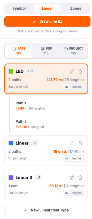
In the Linear Tab
Each rule card shows:
- Path count: Number of paths using this rule
- Total: Length or quantity depending on display mode
- Per-length info: The unit length setting
Expand a rule to see individual paths with their measurements.
Display Mode Toggle
Switch how measurements display:
- m button: Show total length in meters (e.g., "25.50 m")
- lengths button: Show quantity with length (e.g., "4 (25.50 m)")
The toggle appears on each rule card in the Linear tab.
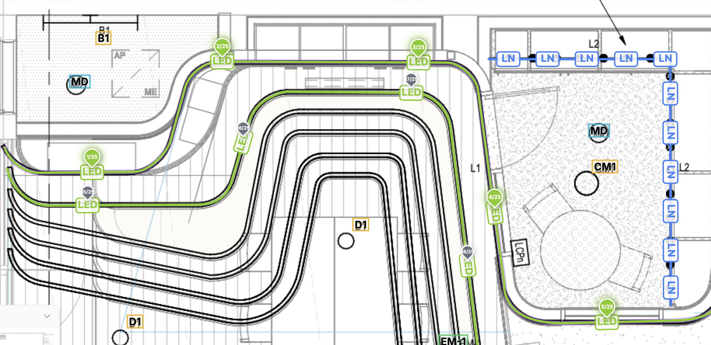
On the PDF Canvas
Paths display as colored lines matching the rule's color. When a path is selected:
- Vertex points appear as draggable circles
- The end vertex shows a (+) extend button
- Hover shows the path's length
In the Legend
When the legend is visible:
- Linear rules appear as a separate section
- Shows rule name, path count, and total measurement
- Individual paths listed with their lengths
- Respects the display mode setting (length vs lengths)
In PDF Export
Exported PDFs include:
- All linear paths drawn on each page
- Legend with linear measurements
- Per-path breakdown with lengths or quantities
In Shared Links
When you share a project:
- Viewers see all linear paths on the drawings
- The Linear tab shows all measurements (read-only)
- Display mode settings are preserved
- Scale settings are included for accurate length display
See Sharing Projects for more details.
Length Calculation
Plan Count calculates real-world lengths using your PDF's scale setting.
How It Works
Real Length = (Pixels on PDF ÷ 72) × Scale Ratio × 0.0254 meters

Example at 1:100 scale:
- 500 pixels on PDF
- = 500 ÷ 72 inches on paper = 6.94 inches
- = 6.94 × 100 real inches = 694 inches
- = 694 × 0.0254 = 17.6 meters
Quantity Calculation
Quantities are calculated by dividing total length by unit length and rounding up:
Quantity Needed = ceil(Total Length ÷ Unit Length)

Example:
- Total path length: 25 meters
- Unit length (roll): 8 meters
- Quantity needed: ceil(25 ÷ 8) = 4 rolls
INFO
Always rounds up because you can't buy partial units. A 25m run needs 4 full 8m rolls.
Length Display Format
Lengths format based on size:
- Very short (< 1cm): Shows decimal centimeters (e.g., "0.5 cm")
- Short (1-99cm): Shows whole centimeters (e.g., "50 cm")
- Long (≥ 1m): Shows meters with decimals (e.g., "1.50 m")
Imperial mode converts meters to feet for display.
Keyboard Shortcuts
| Key | Action |
|---|---|
L | |
K | Select Curve tool (freehand curves) |
Escape | Cancel current path / Deselect |
Enter / Tab | Complete current path |
Delete | Delete selected path |
V |
Tips
Best Practices
- Set scale first - Configure your PDF scale before drawing any paths
- Use descriptive names - Name rules clearly (e.g., "3-core 2.5mm" not just "Cable")
- Draw at centerline - Trace paths along the center of cable routes for accuracy
- Name important paths - Give custom names to paths for easy identification
- Check display mode - Use "lengths" mode when ordering materials
Workflow Example
- Set PDF scale (e.g., 1:100)
- Create rule: "LED Strip", 8m lengths, display as "lengths"
- Draw path along LED route
- Create rule: "Cable Tray", 3m lengths
- Draw multiple paths for tray routes
- Review Linear tab for quantities
- Export PDF with legend showing all measurements
Common Issues
Paths not appearing?
- Make sure a linear rule exists before drawing
- Check that you're in LINEAR tool mode (press L)
Lengths seem wrong?
- Verify your scale setting matches the PDF's actual scale
- Check that the scale ratio is entered correctly
Can't see vertices?
- Click on the path to select it first
- Vertices only show when the path is selected
Can't edit a path?
- Make sure you're in Select mode (press S)
- Click directly on the path line to select it
Curve not smooth?
- Drag further from the line to increase curve intensity
- For tight curves, insert additional vertices first
Wrong display mode?
- Click m/lengths toggle on the rule card
- Changes save automatically
CSV Export
Linear measurements export to CSV with:
- Summary table: Type, Symbol, Total Length, Unit Length, Units Needed, Path Count
- Detail table: Type, Path Name, Length, Units
This allows you to import into spreadsheets for pricing calculations.